![]()
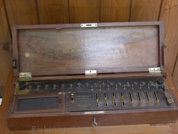
"The
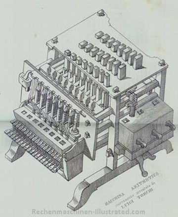
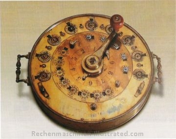
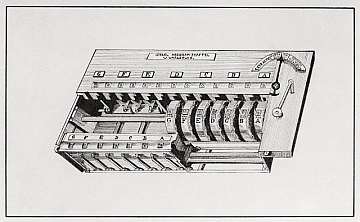
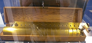
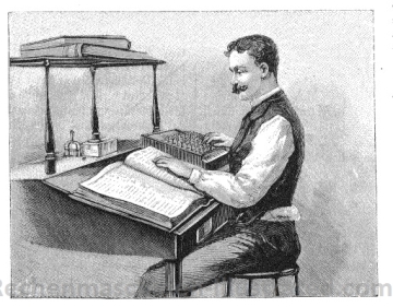
young LUIGI TORCHI (pronounce torki) was a carpenter who, so far as I can
understand, had only been to primery school.
In
1834 he obtained a gold medal for a calculator he had created from pieces of
wood and steel wire. It took him three years to build the first machine. No
mention of his birth. So far as I can understand, his machine did three
operations (sums, subtractions and multiplications).
It
was particularly adapted for products with a common factor. It was built to
multiply numbers of 3 digits with 4 digits. The near 66 millions products that
could be obtained would have represented at least 44 five-hundred page volumes.
Carlino
was the first to report the potential advantages of this machines and various
scientists tried to convince the vice king to finance its improvement. This is
reported in a letter dated 1835 written by Giuseppe Belli and sent to the mathematician
Gabrio Piola.
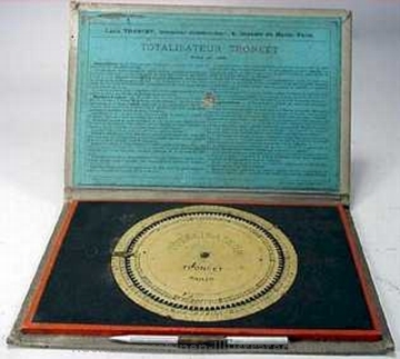
In March 1840 the vice king authorized the purchase of of a metal model of the Torchi machine capable of products of three per four digits for a price of 1 000 Lire."
summary by Christian Barral
Literature:
Annali Universali di Statistica, Milano, 1836
P.Broglia, L.Massio: Il Calcolo Alla Specola Di Brera
| principle |
|
||
| capacity |
|
||
| input | |||
| prod. years | 1834 | ||
| mach. built | |||
| features | |||
| dimensions | |||
| weight | |||
| known s/n | |||
| for bigger and more pictures, click on the picture |
source: La Fama. Giornale di scienze, lettere, arti, industria e teatri' / V.Monnier
June 1840 issue of Kuryer Litewski
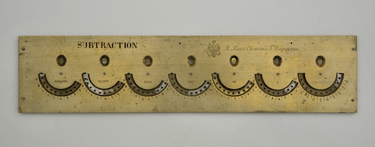
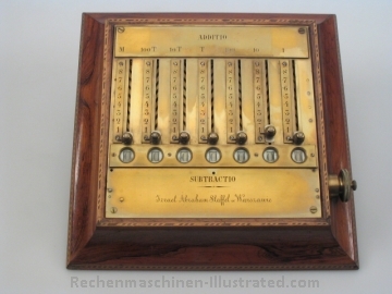
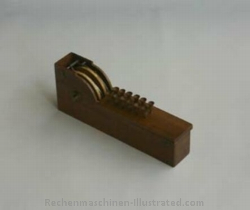
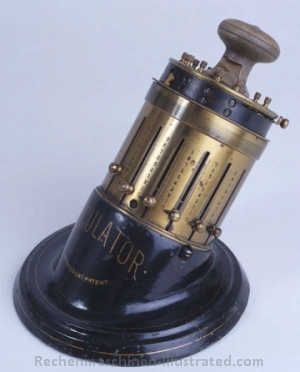
"A Jew S(elig) Slonimski born in Bialystok, recently invented a small machine for calculating, which thanks to its dimensions (length 10 inches,width 3 inches and 1 inch height), comfort, and low price deserves to be widely used. Everybody who knows digits only can, with the help of this machine, make calculations easily, fast, and without need to think. This machine can be seen at the inventor’s residence, where he is now working on a new machine for calculating logarithms. With the help of this machine one can simply and comfortably find the differences of Bruget logarithms,as well as natural logarithms up to 14 decimal digits"
Literature and links:
Polish Contributions to Computing
Georgi Dalakov: Hayyim Selig Slonimski
Stephan Weiss:
Slonimsky's Multiplying Device, an impressive Example for Applied Mathematics
Stephan Weiss:
Successors of Slonimsky's Multiplying Device 1844
Valery Monnier, Walter Szrek, Janusz Zalewski : Hayyim Selig Slonimski and His Adding Devices
Russian Patent for Slonimski's Adder
| principle | Rotary Adder with manually enforced carry |
|
|
| capacity | 7 |
||
| input | stylus | ||
| prod. years | |||
| mach. built | ????? | ||
| features | |||
| dimensions | 35 x 6 x 1.5 cm | ||
| weight | |||
| known s/n | |||
| for bigger and more pictures, click on the picture | |||
| source: Muzeum Uniwersytetu Jagiellonskiego Collegium Maius |
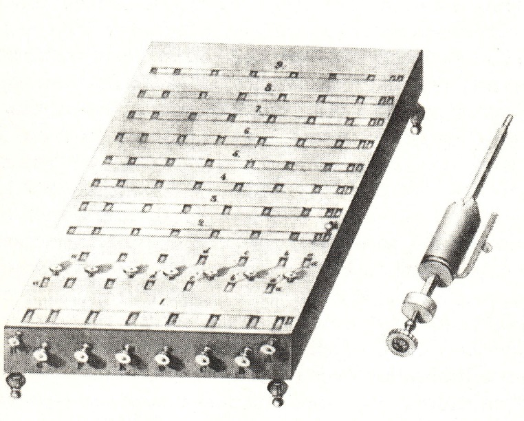
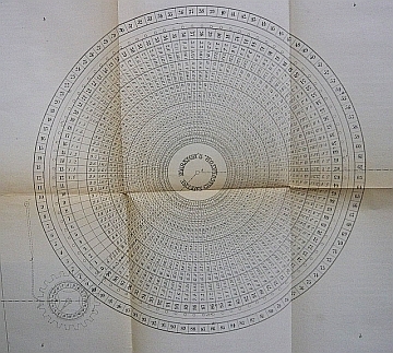
Chayyim Slonimski also designed a multiplication device for which he received a prestigeus Demidov Prize in 1845. This was a non-mechanical device allowing to view multiplication results for all multiplicands (2-9) without mentally adding carry. The device was based on the mathematical theorem invented by him.
| principle | State machine. For each column (decimal position) an index related to the current state of carryovers and multiplicand value points to the results in the next column and the state of carryovers for the following columns. In each column results of the multiplication by a multiplier 2-9 are concurrently seen. |
|
|
| capacity | ????? | ||
| production years | ????? | ||
| machines built | ????? | ||
| features | |||
| for bigger and more pictures, click on the picture | |||
| Trogemann et al.: Computing in Russia. Vieweg 2001 |
Martin (Dtsch), pages 63 - 64
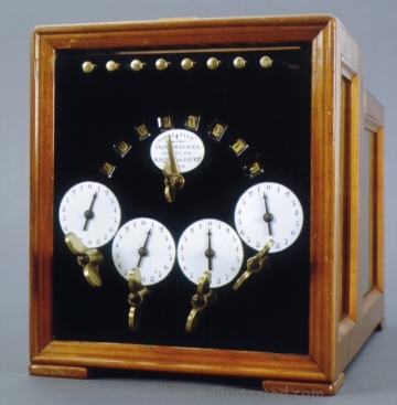
"Dr. Didier Roth, Paris, designed an adding and subtracting machine with a stylus setting mechanism - similar to Pascal’s machine but materially improved."
Literature and links:
Valéry
Monnier: Les machines du Dr.Roth (English version)
| principle | disk calculator |
|
|
| capacity | 2, 8 or 9 |
||
| input | stylus | ||
| prod. years | 1841 | ||
| mach. built | |||
| features | subtraction via complement numbers; also version for English currency | ||
| dimensions | 35 x 6 x 1.5 cm | ||
| weight | |||
| known s/n | |||
| for bigger and more pictures, click on the picture | |||
| source: private collection, France |
Description (in German):
Bericht des Hrn. Theodor Olivier über die Rechenmaschinen des Hrn. Dr. Roth in Paris.
aus dem Bulletin de la Société d'Encouragement, Sept. 1843, S. 411
Dr. Roth also designed a machine that externally resembles Hahn's machine and possesses gears with a variable number of teeth (pinwheel).
| principle | pin wheel |
|
|
| capacity | ????? | ||
| production years | ????? | ||
| machines built | ????? | ||
| features | |||
| for bigger and more pictures, click on the picture | |||
| Exhibit on display at Musée des arts et métiers CNAM, Paris. 60 rue Reaumur 75003 Paris |
Martin (Dtsch), page 64
"No details are known about this machine that was patented in England."
| principle | disk adder |
|
|
| capacity |
|
||
| input | stylus | ||
| prod. years | 1842 | ||
| mach. built | |||
| features | |||
| dimensions | |||
| weight | |||
| known s/n | |||
| for bigger and more pictures, click on the picture | |||
| source: Darek Lipski |
table of interest, patented May 6, 1844
| principle |
|
||
| capacity |
|
||
| input | |||
| prod. years | 1844 | ||
| mach. built | |||
| features | |||
| dimensions | |||
| weight | |||
| known s/n | |||
| for bigger and more pictures, click on the picture | |||
| source: mcon1614 |
Martin (Dtsch), page 65
Literature:
![]() Max Detlefsen: Polnische
Rechenmaschinenerfinder des 19. Jahrhunderts; Wissenschaft und Fortschritt,
26 (1976), pages 86 - 90
Max Detlefsen: Polnische
Rechenmaschinenerfinder des 19. Jahrhunderts; Wissenschaft und Fortschritt,
26 (1976), pages 86 - 90
![]() English translation (done
by Brian
and Pat Stone)
English translation (done
by Brian
and Pat Stone)
source: V.Monnier
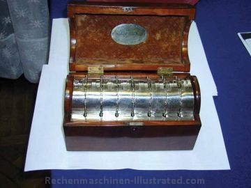
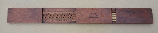
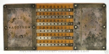
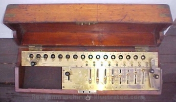
This is a seven-place adding machine made by I. A. Staffel, a Pole.
The machine is the property of the Muzeum Techniki, Warsaw Poland.
| principle | ????? |
|
|
| capacity | 7 | ||
| production years | 1842 | ||
| machines built | ????? | ||
| features | |||
| for bigger and more pictures, click on the picture | |||
| source: W.Szrek |
Staffel also constructed a full 4-specie (plus square-root) calculating machine, not mentioned by Martin.
At the 2. Greifswalder Symposium zur Entwicklung der Rechentechnik,
12. - 14. September 2003, Timo Leipälä gave a talk about "The life and works of W. T. Odhner". He covers some aspects of the development of this Staffel machine:
![]() The life and
works of W. T. Odhner, excerpt
(with permission of the author)
The life and
works of W. T. Odhner, excerpt
(with permission of the author)
| principle | pinwheel ? |
|
|
| capacity | 7 x 7 x 13 | ||
| production years | 1845 | ||
| machines built | |||
| features | |||
| dimensions | 46 x 23 x 10 cm | ||
| for bigger and more pictures, click on the picture | |||
| source: Science Museum, London UK |
Trinks in his book (Trinks F.: Geschichtliche Daten aus der Entwicklung der Rechenmaschine von Pascal bis zur Nova-Brunsviga, Braunschweiger GNC Monatsschrift, 1926, p. 249-276) mentions an adding machine as a third Staffel development:
| principle | ??? |
|
|
| capacity | 7 | ||
| production years | |||
| machines built | |||
| features | 2 species machine | ||
| for bigger and more pictures, click on the picture | |||
| source: Braunschweigisches Landesmuseum, photo: I. Simon | |||
Martin (Dtsch), pages 65 - 66
"This device was made by Maurel and Jayet. The machine is especially well suited for multiplication and division but is also capable of performing additions and subtractions. The operation is very simple. The whole setting mechanism and the result windows are shown in figure 31."
Valéry Monnier: L'Arithmaurel de Maurel & Jayet
![]() Erhard Anthes: Arithmaurel:
Staffelwalzenmaschine von Maurel und Jayet, 1849
Erhard Anthes: Arithmaurel:
Staffelwalzenmaschine von Maurel und Jayet, 1849
| principle | stepped drum |
|
|
| capacity | 8 x 4 x 8 |
||
| input | bars and butterfly knobs | ||
| prod. years | 1849 | ||
| mach. built | few | ||
| features | |||
| dimensions | |||
| weight | |||
| known s/n | |||
| for bigger and more pictures, click on the picture |
source: Braunschweigisches Landesmuseum, photo: I. Simon
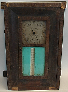
According to NMAH (a part of Smithsonian Institution) website Samuel S. Young of Eaton, Ohio, took out three patents for computing devices. The first one was adding device patented July 24, 1849. The later ones were a rule for calculating interest, patented September 2, 1851 (U.S. patent 8323), and an arithmetical proof rule, patented October 26, 1858 (U.S. patent 21921). The one below is an interest calculating device.
Literature and links:
Young Calculating Machine Patent Model
Young's devices in "History of Computers and Computing, Calculating Tools, ....."
| principle |
|
||
| capacity |
|
||
| input | stylus | ||
| prod. years | |||
| mach. built | |||
| features | |||
| dimensions | 45 x 5 x 1 cm | ||
| weight | |||
| known s/n | |||
| for bigger and more pictures, click on the picture |
source: W. Szrek
On September 26, 1854, a certain Aaron L. Hatfield of Lewisburg, Pennsylvania, took out a US patent no 11726 for machine for adding numbers. There is another calculating device from the time, made by another Hatfield, Jehu, from Glens Falls, New York, patented as Machine for calculating interest in 1844 (patent no 3574), but it seems there is no relation between them.
Literature and links:
Aaron Hatfield's adder in "History of Computers and Computing, Calculating Tools, ....."
| principle |
|
||
| capacity |
|
||
| input | stylus | ||
| prod. years | |||
| mach. built | |||
| features | |||
| dimensions | 25 x 12.5 x 1.5 cm | ||
| weight | |||
| known s/n | 599 | ||
| for bigger and more pictures, click on the picture |
source: W. Szrek
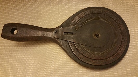
From Giorgi Dalakov: Appleby was born in 1807, all his life lived in Shaftesbury, Devonshire, unmarried, working as Linsey Maker/Hosier and parish clerk, died probably in 1891.
| principle |
|
||
| capacity |
|
||
| input | stylus | ||
| prod. years | |||
| mach. built | |||
| features | |||
| dimensions | 37 x 10.5 x 4 cm | ||
| weight | |||
| known s/n | |||
| for bigger and more pictures, click on the picture |
source: W. Szrek
Martin (Dtsch), page 67
"Hill’s machine, as illustrated in figure 33, shows considerably more similarity with our modern keyboard adding machines than either Parmelee’s or Schilt’s device, yet it never advanced beyond the experimental stage. The model illustrated may be found in the National Museum in Washington. The individual digit wheels have the digits 0 to 9 inscribed around them seven times. These digit wheels are moved by a gear which, in turn, is driven around by the action of depressing a key on the keyboard. There are no overthrow locks. The tens-carry mechanism is similar to that of Pascal’s machine."
| principle | rocker arms |
|
|
| capacity |
|
||
| input | keyboard | ||
| production years | 1857 | ||
| machines built | |||
| features | |||
| known s/n | |||
| for bigger and more pictures, click on the picture |
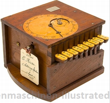
Winter Calculating Machine (1859)
inventor: C.Winter, US patent #23 637
| principle | column adder |
|
|
| capacity |
|
||
| input | keys | ||
| prod. years | 1859 | ||
| mach. built | |||
| features | |||
| dimensions | |||
| weight | |||
| known s/n | |||
| for bigger and more pictures, click on the picture |
© 2004 by Auction Team Breker, Koeln/ Germany
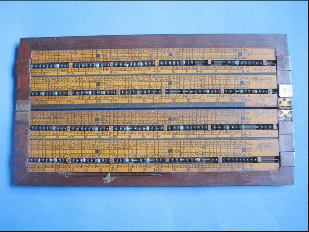
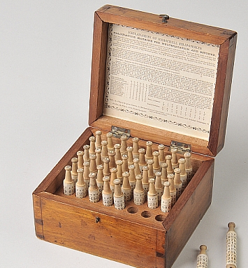
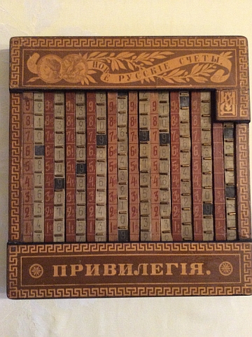
Herschell Filipowski's Calculating Machine for Multiplication and Division, composed of a total of fifty-six wooden calculating rods, each rod with printed paper alphabet letter to crown and printed paper cover with ten columns of figures (each with nine rows).
| principle | table |
|
|
| capacity |
|
||
| input | |||
| prod. years | |||
| mach. built | |||
| features | |||
| dimensions | 12 x 13 x 8 cm | ||
| weight | |||
| known s/n | |||
| for bigger and more pictures, click on the picture | |||
| source: Dominic Winter Auctioneers |
Manufactured by the Fowler Adding Machine Company, New York. Patented by George B. Fowler July 14, 1863. Also marketed under the name "The Universal Adding Machine".
| principle | slide bar-type adder |
|
|
| capacity | 8 x 8 |
||
| input | stylus | ||
| prod. years | 1863 | ||
| mach. built | |||
| features | |||
| dimensions | |||
| weight | |||
| known s/n | |||
| for bigger and more pictures, click on the picture |
source: Oddbits
Martin (Dtsch), page 67
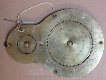
"Designed by C. H. Webb, it consists of two rotable circular disks, one for the numbers up to a hundred, the other one for thousands. The apparatus has automatic tens-carry."
Literature and links:
The Webb Adder in "American Artifacts"
Webb's Adder and Ribbon Adder in "History of Computers and Computing, Calculating Tools, ....."
| principle | circular disks |
|
|
| capacity |
3 x x 4 (up to 4.999) |
||
| input | stylus | ||
| production years | 1868 - ???? | ||
| machines built | |||
| features | |||
| known s/n | |||
| for bigger and more pictures, click on the picture |
source: W.Szrek
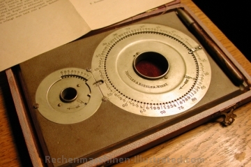
Vienna, Austria (Fa. Soenneckens Schreibwarenfabrik)
it is not clear if Nestler & Roesler was a distributor for Webb or if they produced the adder with or without license.
| principle | circular disks |
|
|
| capacity | up to 4.999 |
||
| input | stylus | ||
| prod. years | |||
| mach. built | |||
| features | |||
| dimensions | 16 x 11 x 1 cm | ||
| weight | 400 g | ||
| known s/n | |||
| for bigger and more pictures, click on the picture | |||
| source: B.Surquin |
French patent from 1893 source: V.Monnier
| principle | cont. ribbons with digits |
|
|
| capacity | 8 x x 8 |
||
| input | stylus | ||
| prod. years | 1893 | ||
| mach. built | |||
| features | |||
| dimensions | |||
| weight | |||
| known s/n | 133 | ||
| for bigger and more pictures, click on the picture | |||
| source: © Peter K. Frei |
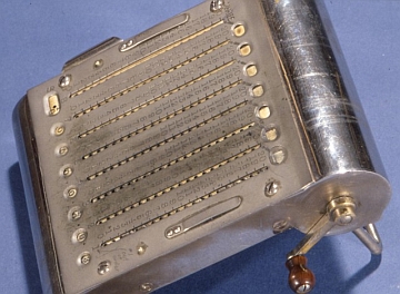
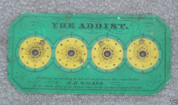
manufacturer: R.H.Walker, New York, USA
| principle | cardboard adder |
|
|
| capacity | 4 x 4 (w/o tc) |
||
| input | stylus | ||
| prod. years | 1869 | ||
| mach. built | |||
| features | |||
| dimensions | 13 x 9 cm | ||
| weight | |||
| known s/n | |||
| for bigger and more pictures, click on the picture |
source: javadogcafe
Martin (Dtsch), page 383
"This is a small adding machine along the lines of Dr. Roth’s machines (figure 30). It has six places in both adding and subtracting viewing windows. During the seventies, the machine was manufactured by Ziegler and McCudry and distributed in Philadelphia. However, it was never widely sold and production has long since ceased."
| principle |
|
||
| capacity |
6 (also 5) |
||
| input | stylus | ||
| production years | 1870 | ||
| machines built | |||
| features | |||
| known s/n | |||
| for bigger and more pictures, click on the picture |
Martin (Dtsch), page 67
"A nine key machine for adding single columns of numbers.
The machine never went beyond the experimental stage."
Martin confused 1870 adding machine with Chapin's 3rd patent from April 1900
Literature and links:
Chapin's devices in "History of Computers and Computing, Calculating Tools, ....."
| principle |
|
||
| capacity |
7 |
||
| input | |||
| production years | 1870 | ||
| machines built | |||
| features | |||
| dimensions | 20 x 15 x 15 cm | ||
| for bigger and more pictures, click on the picture |
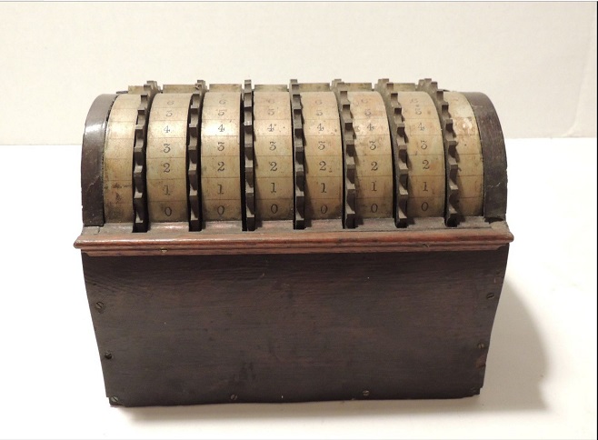
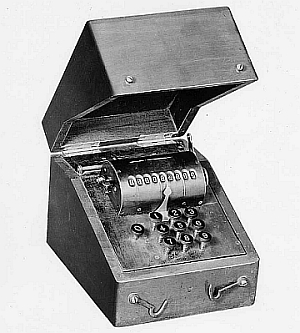
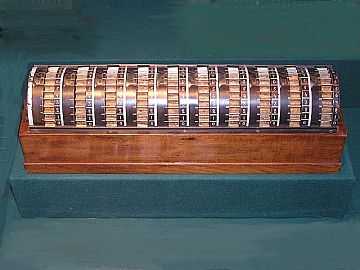
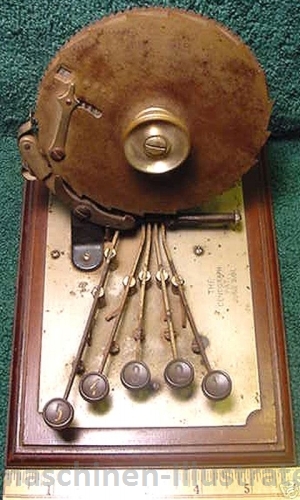
manufacturer: A.J.Petersson, Oslo, Norway
Literature:
E.Anthes: Die zylindrischen Rechenmaschinen von Leupold bis Herzstark, Historische Bürowelt 22, page 16-21 (1988) , IFHB
E.Anthes: Die zylindrische Rechenmaschine von A.J.Petersson, Historische Bürowelt 31, page 17-18 (1991) , IFHB
D.Bölter: Christel Hamann, Paul Haack, Axel Jacob Petersson (2007)
| principle | central stepped drum |
|
|
| capacity | 6 /w/o cr) x 1 x 14, also 5 x 1 x 12 and 6 x 1 x 12 |
||
| input | sliders | ||
| prod. years | 1873 | ||
| mach. built | few | ||
| features | |||
| dimensions | diam. 9.5, height 19 cm | ||
| weight | |||
| known s/n | |||
| for bigger and more pictures, click on the picture |
source: ©Tekniska museet, Stockholm
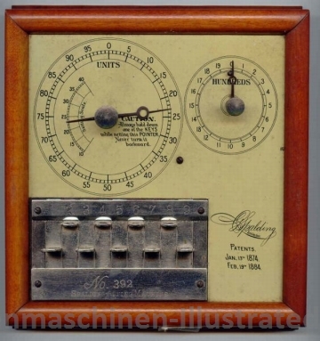
Martin (Dtsch), pages 75 - 80
source: Monroe Calc. Company
"Frank Stephen Baldwin was born on 10 April 1838 in New Hartford. About 1870 he saw the first stepped drum machine and it caught his interest. He decided to build a machine with only one cylinder instead of nine drums. A patent application received at the patent office in Washington on 5 October 1872, which contains exact details and drawings of Baldwin’s machine, specifically of the model that appeared on the market in 1875 that included the gear with the variable number
of teeth. Under the date of 8 September 1873, an improvement on the first model was added to the patent.""Since Odhner’s efforts date back only to 1874, the year he made his first model, it seems now definitely proved that Baldwin was the first to employ, in practice, the gear with the variable number of teeth in a calculating machine. It may be assumed that Odhner reinvented this device at a later date. In any case we have no proof whatsoever that Odhner imitated the Baldwin machine, which, as is widely known, the Americans often claim."
source: Monroe Calc. Company
automatically measurs and records the board feet of lumber and takes four different calculations
| principle | ? |
|
|
| capacity |
|
||
| input | |||
| prod. years | patent: 138 310, April 29, 1873 | ||
| mach. built | |||
| features | |||
| dimensions | |||
| weight | |||
| known s/n | |||
| for bigger and more pictures, click on the picture | |||
| source: Thomas A. Russo |
adding machine (Arithmometer)
| principle | ? |
|
|
| capacity | 6 |
||
| input | |||
| prod. years | patent: 153 522, July 28, 1874 | ||
| mach. built | |||
| features | |||
| dimensions | |||
| weight | |||
| known s/n | |||
| for bigger and more pictures, click on the picture | |||
| source: Pook & Pook, Inc., photographer Kyle Pook |
Cris Vande Velde trip report from the Smithsonian Institution
| principle | pin wheel |
|
|
| capacity | 6 x 8 x 13 |
||
| input | |||
| prod. years | patent: Oct 5, 1872 | ||
| mach. built | |||
| features | |||
| dimensions | |||
| weight | |||
| known s/n | |||
| for bigger and more pictures, click on the picture | |||
| source: Monroe Calc. Company |
| principle |
|
||
| capacity |
|
||
| input | |||
| prod. years | 1905 | ||
| mach. built | |||
| features | |||
| dimensions | |||
| weight | |||
| known s/n | |||
| for bigger and more pictures, click on the picture | |||
| source: Monroe Calc. Company |
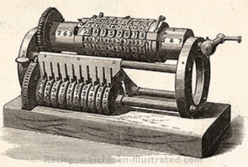
Martin (Dtsch), pages 80 - 82
"This machine was constructed by George B. Grant as early as 1870, but was not publicized until 1877. Additional publications concerning this machine are likely to appear in Brooklyn in the near future.
An upper cylinder is turned by means of a crank and drives a small shaft mounted underneath. A slide on the cylinder, which may be set in eight different positions, carries eight digit rings that may be set for eight or fewer decimal places. With each turn of the crank, the numbers set up in the rings are added to the value set in the ten numeral wheels of the lower shaft."
"The machine illustrated in figure 51 also originates from the same inventor. In front there arc five setting slots with setting levers protruding from them; each slot has two rows of additive and subtractive setting numbers printed adjacent to it. Movement of the setting lever forward or backward moves the racks visible in the drawing. When the crank is turned, the whole carriage is moved forward, and the setting racks mesh with the gears and move them, together with the appropriate numeral wheels. When the carriage is returned, the connection between racks and gears is broken and a successive tens-carry takes place. Zero setting also occurs by rotation of the crank. "
| principle |
|
||
| capacity |
|
||
| input | |||
| prod. years | 1877 | ||
| mach. built | |||
| features | |||
| dimensions | |||
| weight | |||
| known s/n | |||
| for bigger and more pictures, click on the picture |
Diakov (Diakoff, Diakow, Djakow) (1878)
similar to Webb Ribbon Adder and Bassett Adder
| principle | ribbon adder |
|
|
| capacity | 10 x x 10 |
||
| input | stylus | ||
| prod. years | 1878 | ||
| mach. built | |||
| features | 2 species | ||
| dimensions | 33 x 31 x 3 cm | ||
| weight | |||
| known s/n | |||
| for bigger and more pictures, click on the picture | |||
| source: permission granted |
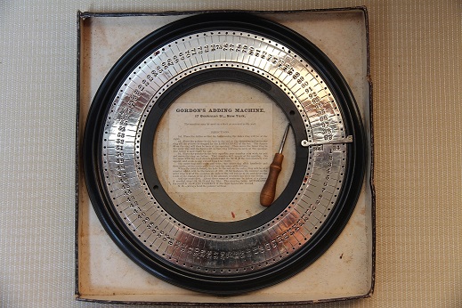
George P. Gordon was granted several patents between 1850 and 1875 in printing presses
| principle | circular adder |
|
|
| capacity | 9999 |
||
| input | stylus | ||
| prod. years | 1878 | ||
| mach. built | more than 30 | ||
| features | only adding | ||
| dimensions | |||
| weight | |||
| known s/n | |||
| for bigger and more pictures, click on the picture | |||
| source: permission granted |
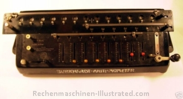
Martin (Dtsch), page 82 - 87 & 400 - 401
"In I876 C. Dietzschold, an engineer in the town of Glashütte, set out to build a multiplication machine. He encountered difficulties, however, and asked for help from one of his schoolmates, Arthur Burkhardt, another engineer who was then serving his time in the army. Burkhardt came to Glashütte in 1878, shortly after Dietzschold had supplied one of his machines to the Royal Prussian Statistical Office. The statistical office found that the machine did not operate to their full satisfaction. A year later Burkhardt replaced this machine with two others constructed according to the stepped drum system (Thomas-Colmar) and thus laid the foundation for the calculating machine industry in Germany. Soon afterward Professor Dr. Reuleaux confirmed that Burkhardt's product excelled the French one in many ways. A number of machines were produced for government authorities, insurance companies, and the like, but the demand for such machines was still so insignificant that Burkhardt had to turn to the manufacture of other articles and, in fact, had to leave Glashütte for Braunschweig (during which time he was active in an entirely different line). He later returned to Glashütte and again devoted his time to the manufacture of calculating machines, which were becoming popular in commercial firms, manufacturing enterprises, and banks. Burkhardt is generally regarded as the founder of the calculating machine industry in Germany, and in the course of years he managed to keep improving his product so that, even today, it is still very popular and meets with increasing sales. Burkhardt died on 21 July 1918.
The "Erste Glashütter Rechenmaschinenfabrik von Arthur Burkhardt in Glashütte" merged, in 1920, with the Glashütter Rechenmaschinenfabrik, Saxonia, also in Glashütte, so that nowadays the Saxonia machine is manufactured by the same firm. The name of the new firm is Vereinigte Glashütter Rechenmaschinenfabriken, Tachometer- und feinmechanische Werkstatt, Glashütte, Sachsen."
On Aug. 28, 1929, the company went out of business.
| principle | stepped drum |
|
|
| capacity |
6 x 7 x 12, 8 x 9 x 16, 10 x 11 x 20 |
||
| input | sliders | ||
| production years | ca. 1880 - 1910 | ||
| machines built | ca. 2.500 | ||
| features | |||
| known s/n | 36 to 2.471 | ||
| for bigger and more pictures, click on the picture |
source: W.Szrek
| principle | stepped drum |
|
|
| capacity |
10 x 9 x 16, 10 x 7 x 13, 10 x 11 x 20, 8 x 7 x 13 |
||
| input | sliders | ||
| production years | ca. 1920 - 1926 | ||
| machines built | |||
| features | |||
| known s/n | 9.409, 9.731 | ||
| for bigger and more pictures, click on the picture |
source: R.Rehbein
| principle | stepped drum |
|
|
| capacity |
6 x 7 x 12, 10 x 11 x 20 |
||
| input | sliders | ||
| production years | from 1905 | ||
| machines built | |||
| features | |||
| known s/n | 7.325, 7.775 | ||
| for bigger and more pictures, click on the picture |
Harts Mercantile Computing Machine (1878)
inventor: William Hart, US patent #199 289, Jan 15, 1878
Literature and links:
![]() US patent #199 289 Improvement in
calculators
US patent #199 289 Improvement in
calculators
![]() Peggy Aldrich Kidwell:
American Adders: Circles and Bands, ETCetera pages 3 - 6, #31, June 1995
Peggy Aldrich Kidwell:
American Adders: Circles and Bands, ETCetera pages 3 - 6, #31, June 1995
| principle | disk adder |
|
|
| capacity |
|
||
| input | stylus | ||
| prod. years | 1878 | ||
| mach. built | |||
| features | |||
| dimensions | 12.4 cm diameter | ||
| weight | |||
| known s/n | |||
| for bigger and more pictures, click on the picture |
source: D.Amidon
J.F.Hellström, Nykoping (Sweden); patent 10/7 1879
![]() how to use the Hellström adder (source: K.Badur)
how to use the Hellström adder (source: K.Badur)
| principle | adder |
|
|
| capacity | up to 99.999 |
||
| input | |||
| prod. years | 1879 | ||
| mach. built | |||
| features | |||
| dimensions | 15,5 cm diam., 6,5 cm height | ||
| weight | |||
| known s/n | |||
| for bigger and more pictures, click on the picture | |||
| source: auktionsverket.se |
source: D.Amidon
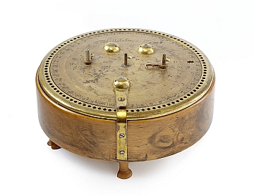
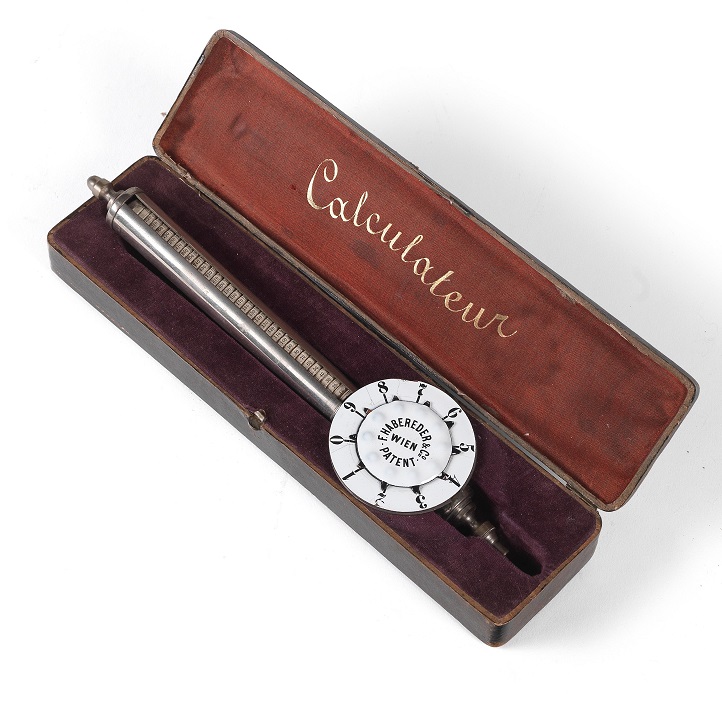
patented 1880 by Caroline Saruber and F. Habereder, manufactured by F. Habereder & Co Vienna
| principle | spiral adder |
|
|
| capacity | up to 329 |
||
| input | wheel | ||
| prod. years | 1880 | ||
| mach. built | |||
| features | |||
| dimensions | length 24 cm | ||
| weight | |||
| known s/n | |||
| for bigger and more pictures, click on the picture | |||
| source: Auction House Dorotheum, Vienna |
Martin (Dtsch), page 88 - 91
"This is a combined adding, subtracting, multiplying, and dividing machine designed by the Russian mathematician Tschebicheff. Only one example of the machine was built, in Paris, and it may be found in the Conservatoire des Arts et Métiers. The machine does not use any springs."
Literature and links:
Mechanisms by Tchebyshev (with movie)
pictures show the first model of the adding machine from the History Museum of St. Petersburg, a second model is in CNAM, Paris
| principle |
|
||
| capacity |
|
||
| input | |||
| prod. years | 1882 | ||
| mach. built | |||
| features | |||
| dimensions | |||
| weight | |||
| known s/n | |||
| for bigger and more pictures, click on the picture | |||
| source: Andrew Butko (http://commons.wikimedia.org/wiki/File:Арифмометр.jpg) |
Martin (Dtsch), page 91
"From 1883 to 1886 Layton’s Arithmometer was manufactured and sold by Charles and Edwin Layton on Farrington Road in London. This was the first English stepped drum machine. Later Tate, a sales agent for the machine, improved it. It was sold under the name Tate from 1907 until 1914. "
| principle | stepped drum |
|
|
| capacity | various | ||
| input | sliders | ||
| prod. years |
1883 - 1886 Layton 1907 - 1914 Tate |
||
| mach. built | |||
| features | |||
| dimensions | |||
| weight | |||
| known s/n | 1.222 | ||
| for bigger and more pictures, click on the picture | |||
| source: Judd |
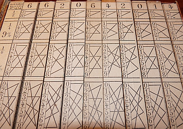
further development of Napier's bones, direct display of the result, no manuell adding necessary
Literature and links:
Die Multiplizierstäbe von Genaille und Lucas
Les Réglettes Financières
| principle |
|
||
| capacity | |||
| input | |||
| prod. years |
1883 |
||
| mach. built | |||
| features | |||
| dimensions | |||
| weight | |||
| known s/n | |||
| for bigger and more pictures, click on the picture | |||
| source: Valéry Monnier |
Martin (Dtsch), page 92
"This is a single-column adding machine with nine slides, situated in one row, for setting up the individual digits. Instead of the customary counting gears, this machine has mounted on its surface two numeral dials, each with a pointer. The large dial on the left (figure 62) is for the numbers 1 to 99; the hundred is automatically transferred to the smaller dial o n the right.
The machine was never put into production and remained unknown in practice."
| principle |
|
||
| capacity | ???? | ||
| production years |
1884 |
||
| machines built | ????? | ||
| features | |||
| for bigger and more pictures, click on the picture |
Martin (Dtsch), page 93 - 94
"In this machine the multiplicand and divisor are set with the aid of the slides shown in figure 63. The result mechanism and revolution counter are situated upon a circular disc in the center. This arrangement has the advantage that a division that does not end without remainder may be continued for any selected number of places, whereas the stepped drum machine or the pinwheel machine only permit division to be carried on over a limited number of places. The machine is provided with a zero-setting device with which some, or all of the windows may be set to zero.
The machine was manufactured by Blakey, Emmot. and Company in Halifax."
| principle | stepped drum |
|
|
| capacity | 8 x 20, variable split between result and counter register |
||
| input | sliders | ||
| prod. years | 1885 | ||
| mach. built | |||
| features | |||
| dimensions | 48 x 41 x 15 cm | ||
| weight | 20 kg | ||
| known s/n | |||
| for bigger and more pictures, click on the picture | |||
| source: O.Mundy |
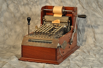
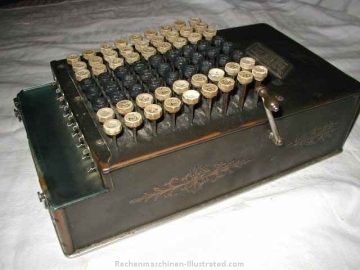
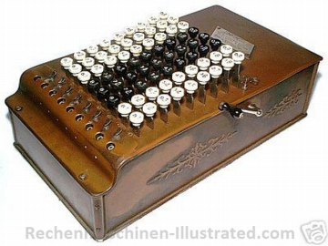
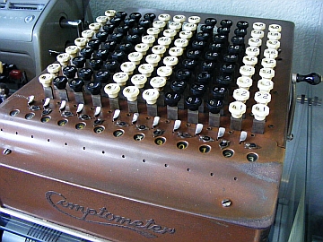
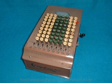
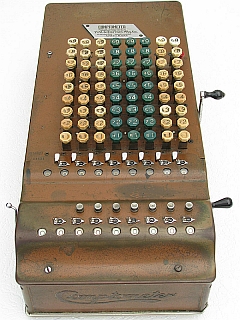
Martin (Dtsch), page 94 - 99 & 401
"Dorr E. Felt was employed as a mechanic in Chicago in 1884 when he was twenty-two years old. He spent his free time on experiments making a calculating machine. In 1885 his first machine, which admittedly was rather primitive, was completed. It is illustrated in figure 64, and since it was built into an old macaroni box. it received the name macaroni box model. This model is still in existence today. In November 1887 the firm Felt and Tarrant was founded. It was registered in January 1889. and since that time the firm has been manufacturing Comptometer calculating machines under the personal management of the inventor."
Literature and links:
Jay M. Goldman has a very nice collection of Comptometer on his web page.
Brooke W. Boering maintains the Comptometer home page. Here you find everything you want to know about the Comptometer.
see also Bell Punch Comptometer
La Nature (April 1896) source: Valery Monnier
| principle | rocker arm |
|
|
| capacity | 8, 10 or 12 |
||
| input | full keyboard | ||
| prod. years | 1887 - 1903 | ||
| mach. built | ca. 6.500 | ||
| features | also models for British currency | ||
| dimensions | |||
| weight | |||
| known s/n | 61, 71, 3.676 | ||
| for bigger and more pictures, click on the picture | |||
| source: S.Roube |
| principle | rocker arm |
|
|
| capacity | various |
||
| input | full keyboard | ||
| prod. years | patent 1889 | ||
| mach. built | |||
| features | integrated printer | ||
| dimensions | |||
| weight | |||
| known s/n | |||
| for bigger and more pictures, click on the picture | |||
| source: Thomas A. Russo |
| principle | rocker arm |
|
|
| capacity | 8, 10 or 12 |
||
| input | full keyboard | ||
| prod. years | 1904 - 1906 | ||
| mach. built | ca. 2-3.000 | ||
| features | |||
| dimensions | |||
| weight | |||
| known s/n | 15.000 and higher | ||
| for bigger and more pictures, click on the picture | |||
| principle | rocker arm |
|
|
| capacity | 8, 10 or 12 |
||
| input | full keyboard | ||
| prod. years | from 1915 | ||
| mach. built | |||
| features | |||
| dimensions | |||
| weight | |||
| known s/n | 100,000 - ? | ||
| for bigger and more pictures, click on the picture |
| principle | rocker arm |
|
|
| capacity | 8, 10 or 12 |
||
| input | full keyboard | ||
| prod. years | from 1920 | ||
| mach. built | |||
| features | |||
| dimensions | |||
| weight | |||
| known s/n | ca. 200.000 and higher | ||
| for bigger and more pictures, click on the picture | |||
| source: M.Meissner |
| principle | rocker arm |
|
|
| capacity | 8, 10 or 12 |
||
| input | full keyboard | ||
| prod. years | from 1926 | ||
| mach. built | |||
| features | also models for British currency | ||
| dimensions | |||
| weight | |||
| known s/n | ca. 245.000 and higher | ||
| for bigger and more pictures, click on the picture | |||
| source: HJ.Denker |
| principle | rocker arm |
|
|
| capacity | 8, 10 or 12 |
||
| input | full keyboard | ||
| prod. years | from 1930 | ||
| mach. built | |||
| features | sub-total and grand-total | ||
| dimensions | |||
| weight | |||
| known s/n | J316.821 S1.131 | ||
| for bigger and more pictures, click on the picture | |||
| source: H.van Noort |
Martin (Dtsch), page 100 - 101
"Professor Dr. E. Selling of Würzburg designed a calculating machine in which the tiresome turning of the crank, and also the jerky tens-carry, was successfully avoided by employment of the device known as the Nuremberg shears (also known as a stork bill).
The machine consists of two separate mechanisms that are brought into joint action during the operation. The two parts are:
I . The Nuremberg shears with toothed racks and keyboard for setting the multiplicand.
2 . The gears and numeral wheels. all mounted upon a common shaft and adapted to receive the longitudinal movement of the racks and convert it into a rotating movement. The numeral wheels are connected with one another by so-called planetary gears for the purpose of tens-carry. Thus a malfunction due to spring obstructions is rendered impossible.
The actual calculating occurs by opening and closing the Nuremberg shears by means of a hand ring, the magnitude of such movement being determined by the multiplier."
| principle | Nuremberg shears |
|
|
| capacity | 6 (w/o cr) x 6 (w tc) x 12 |
||
| input | full keyboard | ||
| prod. years | 1886 | ||
| mach. built | |||
| features | |||
| dimensions | |||
| weight | |||
| known s/n | 20 | ||
| for bigger and more pictures, click on the picture |
source: Braunschweigisches Landesmuseum, photo: I. Simon
adding machine; inventor: E.W.Watson, McLean, NY (USA)
| principle |
|
||
| capacity |
|
||
| input | stylus | ||
| prod. years | 1886 | ||
| mach. built | |||
| features | |||
| dimensions | |||
| weight | |||
| known s/n | |||
| for bigger and more pictures, click on the picture | |||
| source: typebar |
Martin (Dtsch), page 102 - 103
"Designer: Otto Büttner, Kaulbachstr. 18, Dresden, Sales agency: Wilhelm Brückner, Dresden.
In appearance the machine resembles the contemporary stepped drum machines."
this is a pin wheel machine.
| principle | pin wheel |
|
|
| capacity | various |
||
| input | thumb wheel | ||
| prod. years | 1888 | ||
| mach. built | |||
| features | |||
| dimensions | |||
| weight | |||
| known s/n | 93 | ||
| for bigger and more pictures, click on the picture | |||
| source: Deutsches Museum, München; photo: W.Szrek |
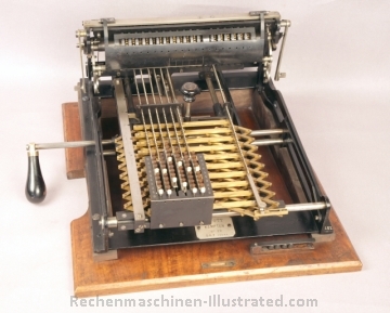
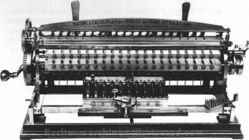
Martin (Dtsch), page 103 - 109
"All calculating machines described so far have implemented multiplication by continued addition and division by continued subtraction. Leon Bollée, born 1 April 1870, constructed in the course of three months (from February until April 1888) a calculating machine in which the multiplication table was mechanically represented for the first time. In other words, he created the multiplication body that we find today in the Millionaire machine, in the Moon-Hopkins machine, and in the Kuhrt machine, although the various manufacturers designed it in slightly different forms."
A very nice movie and animation about the Bollée machine can be found on this web site of the CNAM Musée des arts et métiers (Quicktime required, click on the word VIDEO in the right, lower corner)
| principle | multiplication body |
|
|
| capacity | various | ||
| prod. years | 1888 - 1892 (?) |
||
| mach. built | few | ||
| features | |||
| for bigger and more pictures, click on the picture |
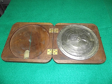
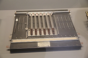
Arithmographe de Bollée (1895)
This instrument combines slide adder mechanically connected with a series of overlapping multiplication rods. Partial results (of multiplication) are not given in form of digits, like on Napier’s bones, but by the positions of adding wings (coulisses d’addition).
| principle | slide adder |
|
|
| capacity | |||
| prod. years | 1895 |
||
| mach. built | |||
| features | |||
| for bigger and more pictures, click on the picture |
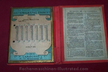
Martin (US) not mentioned in Martin
designer: L.Troncet, manufacturer: P.Larousse, Paris, France
| principle | sliders |
|
|
| capacity |
7 x x 7 |
||
| input | pen | ||
| production years | ca. 1890 | ||
| machines built | ??? | ||
| features | addition and subtraction | ||
| known s/n | |||
| for bigger and more pictures, click on the picture |
| principle |
|
||
| capacity |
|
||
| input | pen | ||
| production years | ca. 1895 | ||
| machines built | |||
| features | |||
| known s/n | |||
| for bigger and more pictures, click on the picture |
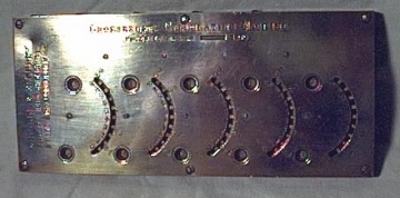
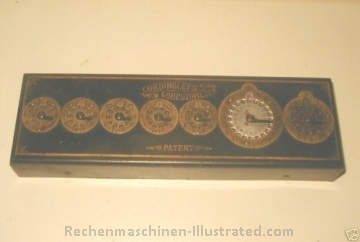
Cordingley's Computometer Patent Adding Machine, manufactured by W.G.Cordingley & Co., London
| principle |
|
||
| capacity |
|
||
| input | stylus | ||
| prod. years | 1890 - 1910 | ||
| mach. built | |||
| features | English currency | ||
| dimensions | |||
| weight | |||
| known s/n | 1 072 | ||
| for bigger and more pictures, click on the picture |
source: John Homefish
small adder, constructed by Arthur E. Shattuck, San Francisco; patented June 9, 1891.
Bob Otnes, Palo Alto, California
Vortrag, gehalten beim 2. Greifswalder Symposium zur Entwicklung der
Rechentechnik 12. - 14. September 2003, erschienen in Girbardt/Schmidt
9-2003
published also in Rechnerlexikon
| principle | ??? |
|
|
| capacity | ??? | ||
| production years | 1891 - ? |
||
| machines built | ??? | ||
| features | |||
| for bigger and more pictures, click on the picture |
source: Jim Lynard
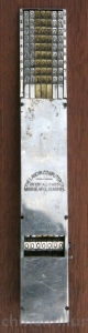
inventor: P.J.Landin, US patent #482 312 from 1891
"grandfather" of the Rapid Computer and Comptator.
Peggy Aldrich Kidwell : "Yours for Improvement'-The Adding Machines of Chicago, 1884-1930" in IEEE Annals of the History of Computing Juli - Sept. 2001, pp. 3 - 21 :
| principle | chain adder |
|
|
| capacity | 7 x x 7 |
||
| input | stylus | ||
| prod. years | from 1891 | ||
| mach. built | |||
| features | |||
| dimensions | |||
| weight | |||
| known s/n | |||
| for bigger and more pictures, click on the picture |
source: W.Szrek
![]()
important copyright note:
© 2003-2011 Herbert Schneemann and Walter Szrek.
All the pictures, articles and any other material are the copyright of the mentioned source.
Please
do not copy or reprint without a
written permission.
last updated: 26-Nov-13